

C# Wireless Network Adapter Disable/Enable - 무선 네트워크 어댑터 활성화/비활성화 2
C# 2022. 1. 4. 20:55 |반응형
2022.01.04 - [C#] - C# Wireless Network Adapter Disable/Enable - 무선 네트워크 어댑터 활성화/비활성화 1
의 소스를 조금 더 심플하게 수정해 보자.
|
1
2
3
4
5
6
7
8
9
10
11
12
13
14
15
16
17
18
19
20
21
22
23
24
25
26
27
28
29
30
31
32
33
34
35
36
37
38
39
40
41
42
43
44
45
46
47
48
49
50
51
52
53
54
55
56
57
|
using System;
using System.Collections.Generic;
using System.Linq;
using System.Text;
using System.Threading.Tasks;
using System.Management;
namespace ConsoleApp1
{
class Program
{
static void Main(string[] args)
{
ListAllNetworkAdapters();
}
private static void ListAllNetworkAdapters()
{
try
{
ManagementObjectSearcher searcher =
new ManagementObjectSearcher("root\\CIMV2", "SELECT * FROM Win32_NetworkAdapter");
foreach (ManagementObject queryObj in searcher.Get())
{
if (queryObj["Name"].ToString().Contains("Wireless"))
{
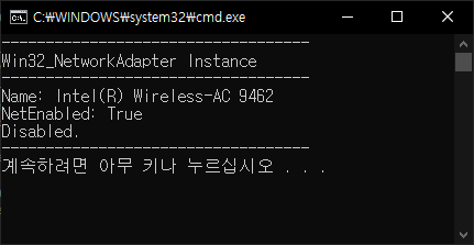
Console.WriteLine("-----------------------------------");
Console.WriteLine("Win32_NetworkAdapter Instance");
Console.WriteLine("-----------------------------------");
Console.WriteLine("Name: {0}", queryObj["Name"]);
Console.WriteLine("NetEnabled: {0}", queryObj["NetEnabled"]);
if ((bool)queryObj["NetEnabled"])
{
queryObj.InvokeMethod("Disable", null); // 관리자 권한 실행 필요
Console.WriteLine("Disabled.");
}
else
{
queryObj.InvokeMethod("Enable", null); // 관리자 권한 실행 필요
Console.WriteLine("Enabled.");
}
Console.WriteLine("-----------------------------------");
}
}
}
catch (ManagementException e)
{
Console.WriteLine("An error occurred while querying for WMI data: " + e.Message);
}
}
}
}
|
소스를 입력하고 빌드한다.
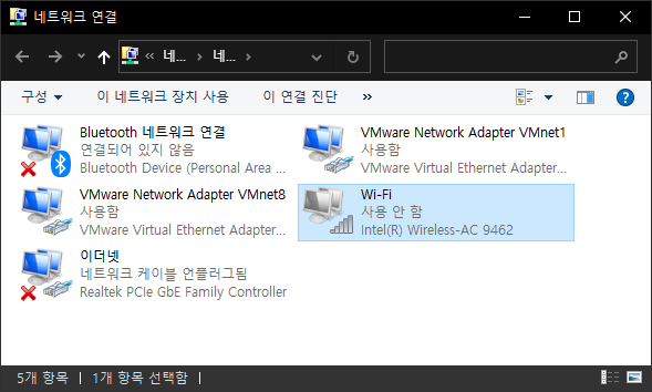
※ 이 프로그램은 관리자 권한으로 실행해야 한다.
반응형
'C#' 카테고리의 다른 글
| C# Run As Administrator - 관리자 권한으로 실행하기 (0) | 2022.01.05 |
|---|---|
| C# Network Adapter IP Address Release/Renew With ipconfig - ipconfig 명령 네트워크 어댑터 아이피 주소 구성 삭제/갱신 (0) | 2022.01.04 |
| C# Wireless Network Adapter Disable/Enable - 무선 네트워크 어댑터 활성화/비활성화 1 (0) | 2022.01.04 |
| C# Finding All Network Adapters Using WMI - 모든 네트워크 어댑터 찾기 (0) | 2022.01.04 |
| C# Call C# DLL in C++ - C++에서 C# 라이브러리 사용하기 (0) | 2022.01.02 |


