반응형

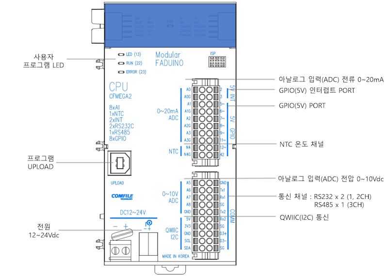
CFMEGA2는 2개의 RS232 통신 채널이 있다. 

컴퓨터와 USB로 연결하고 시리얼 통신을 하는 경우는 아래 링크의 예와 같이 그냥 Serial 클래스를 사용하면 되지만 RS232 통신을 위한 핀(TX, RX, SG)을 직접 사용해 통신하는 경우는 Serial1, Serial2 클래스를 사용해야 한다.


2021.03.24 - [Embedded] - Digital Temperature Sensor DS18B20 with Arduino - 아두이노 방수 온도 센서


Serial1(Tx1, Rx1, SG)에 연결


#include <OneWire.h>
#include <DallasTemperature.h>
#include <LowPower.h>

// Data wire is plugged into port 2 on the Arduino
#define ONE_WIRE_BUS 2
#define TEMPERATURE_PRECISION 9 // Lower resolution

// Setup a oneWire instance to communicate with any OneWire devices (not just Maxim/Dallas temperature ICs)
OneWire oneWire(ONE_WIRE_BUS);

// Pass our oneWire reference to Dallas Temperature.
DallasTemperature sensors(&oneWire);

int numberOfDevices; // Number of temperature devices found
uint8_t sensor[3][8] = { { 0x28, 0xB8, 0x22, 0x94, 0x65, 0x25, 0x06, 0x5F},
                         { 0x28, 0xBB, 0x38, 0x60, 0x65, 0x25, 0x06, 0xB8},
                         { 0x28, 0x82, 0xBD, 0x0B, 0x92, 0x25, 0x06, 0x29} };

void setup(void)
{
  // start Serial1 port
  Serial1.begin(9600);
  
  // Start up the library
  sensors.begin();

  // Grab a count of devices on the wire
  numberOfDevices = sensors.getDeviceCount();

  // locate devices on the bus
  Serial1.print("Locating devices... ");
  Serial1.print("Found ");
  Serial1.print(numberOfDevices, DEC);
  Serial1.println(" devices.");

  // report parasite power requirements
  Serial1.print("Parasite power is: ");
  if (sensors.isParasitePowerMode())
    Serial1.println("ON");
  else
    Serial1.println("OFF");
  
  Serial1.print("Setting resolution to ");
  Serial1.println(TEMPERATURE_PRECISION, DEC);

  // set the resolution to 9 bit per device
  for (uint8_t i = 0; i < numberOfDevices; i++){
    if (!sensors.setResolution(sensor[i], TEMPERATURE_PRECISION))
      Serial1.print("Failed to set resolution");
  }
  
  for (uint8_t i = 0; i < numberOfDevices; i++){
    Serial1.print("Sensor ");
    Serial1.print(i);
    Serial1.print(" Resolution: ");
    Serial1.println(sensors.getResolution(sensor[i]), DEC);
  }  
}

// function to print the temperature for a device
void printTemperature(DeviceAddress deviceAddress, uint8_t id)
{
  float tempC = sensors.getTempC(deviceAddress);
  if (tempC == DEVICE_DISCONNECTED_C)
  {
    Serial1.println("Error: Could not read temperature data");
    return;
  }
  Serial1.print(id);
  Serial1.print(": ");
  Serial1.print(tempC);  
  Serial1.println("°C");
}

void loop (void)
{
  // call sensors.requestTemperatures() to issue a global temperature
  // request to all devices on the bus
  sensors.requestTemperatures();

  for (uint8_t i = 0; i < numberOfDevices; i++){
    printTemperature(sensor[i], i);
  }
  Serial1.println("-----------");
  Serial1.flush();
  // Serial1.print()가 종료되어도 데이터를 전송하는데 시간이 걸린다.
  // 데이터를 다 보내기도 전에 LowPower.powerDown()가 실행되면 아두이노가 바로 잠들어 버린다.
  // 아두이노가 잠들기 전에 Serial1.flush()로 시리얼 버퍼에 남은 데이터를 모두 전송해야 한다.
  // digitalWrite() 등으로 LED나 다른 하드웨어를 작동시키고 있었다면 delay(100) 같은 명령으로
  // 반응할 수 있는 최소한의 시간을 주어야 한다.

  LowPower.powerDown(SLEEP_1S, ADC_OFF, BOD_OFF);
  // SLEEP_1S: 아두이노를 1초 동안 잠들게 한다.
  // ADC_OFF: 잠자는 동안 아날로그 센서를 읽는 기능(ADC)을 꺼서 전기를 아낀다.
  // BOD_OFF: 저전압 감지 기능(BrownOut Detection)을 꺼서 전기를 더 많이 아낀다.
}


Serial1 클래스를 사용해 코드를 작성한다.


반응형
Posted by J-sean
:
반응형

CFMEGA2는 노이즈 보호를 위해 8개(5, 6, 7, 8, 9, 11, 12, 42)의 지정된 GPIO 단자만 나와 있다.


하드웨어 SPI 핀이 필요하다면 CF-SHIELD를 연결해야 한다. 소프트웨어 SPI 통신을 한다면 아무 GPIO 핀을 이용해도 된다.


CF-SHIELD는 CFMEGA2에 나와 있지 않은 4번, 10번 GPIO 및 하드웨어 SPI 통신 핀, 그리고 몇 개의 전원선을 가져온다. 그 외의 다른 핀들은 연결되지 않는다.


반응형
Posted by J-sean
:
반응형

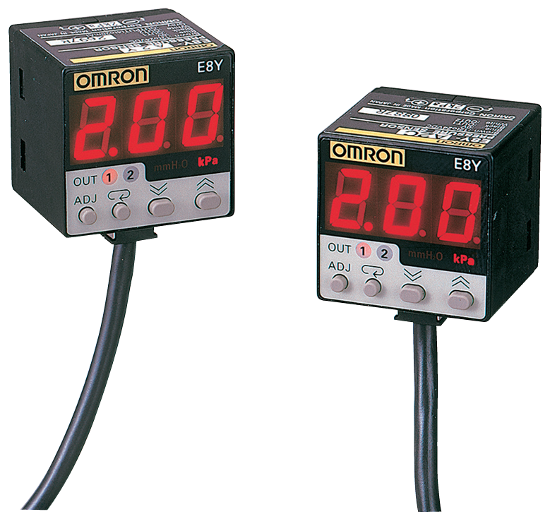
CFMEGA2에서 OMRON E8Y 압력 센서를 사용해 보자.


정확히 이 모델을 사용한 건 아니다.


// CFMEGA2에서 A0~A3은 0~20mA 전류값을 0~1023의 디지털 값으로 변환한다. (Analog to Digital Converter)
// OMRON E8Y 압력 센서는 압력에 따라 4~20mA의 아날로그 전류를 출력한다.
//
// 4mA의 ADC 값: 약 204 (1023의 20%)
// 20mA의 ADC 값: 1023
//
// 그럼 이론적으로는 CFMEGA2에서 204~1023의 값을 감지할 것이다. (범위: 819)
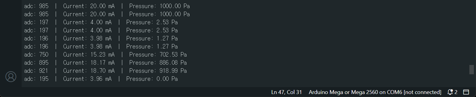
// 하지만 압력 센서를 연결하고 압력을 가하지 않은 상태의 값을 확인해 보면 195,
// 센서가 감지할 수 있는 최대 압력을 가한 상태의 값을 확인해 보면 985가 나온다. (범위: 790)
//
// 실제 값에 맞게 보정해 주어야 한다.

const int sensorPin = A0;  // 0~20mA 전용 입력 핀에 연결 (회색 선).
const float maxPressure = 1000.0f; // 압력 센서 데이터시트에 기재된 최대 측정 압력값. (1,000Pa)
const float maxCurrent = 20.0f; // 압력 센서 데이터시트에 기재된 최대 측정 전류값.
const int initialADCValue = 195; // 압력이 없을때 ADC 값으로 195가 들어온다.
const int maxADCValue = 985; // 최대 압력일때 ADC 값으로 985가 들어온다.

void setup() {
  Serial.begin(9600);
  Serial.println("----------- CFMEGA2 Pressure Measure Start -----------");
}

void loop() {
  int adcValue = analogRead(sensorPin);
  
  // 센서 단선 또는 전원 오류 확인 (4mA 미만 확인)
  // 오차를 감안해 ADC 값이 190(약 3.7mA) 미만으로 떨어지면 오류로 간주
  if (adcValue < 190) {
    Serial.println("Error: Weak Sensor Signal. Check the sensor or the cable.");
  } else {
    // ADC 값(204~1023)을 압력(0~maxPressure)으로 비례 변환
    float pressure = (adcValue - initialADCValue) * (maxPressure / (maxADCValue - initialADCValue));
    // 값 보정: 실제 센서에 압력이 전혀 안 걸려 있을 때 출력되는 전류가 정확히
    // 4mA(ADC 204)가 아닐 수 있다. 초기값이 미세하게 맞지 않는다면 initialADCValue 값을
    // 실제 측정된 초기 ADC 값으로 조금씩 수정하여 보정한다.
    // 내 경우엔 195다. 최대 압력이 걸렸을때는 1023이 아니라 985다.

    // 센서에서 현재 출력되는 전류(mA) 역산
    float current_mA = adcValue * (maxCurrent / maxADCValue);
    
    Serial.print("adc: ");
    Serial.print(adcValue);
    Serial.print("  |  Current: ");
    Serial.print(current_mA, 2); // 소수점 둘째 자리까지 출력
    Serial.print(" mA  |  Pressure: ");
    Serial.print(pressure, 2);
    Serial.println(" Pa");
  }
  
  delay(1000); // 1초 대기
}


센서 데이터가 표시된다.


이번엔 아스키 문자가 아닌 바이너리 데이터를 전달해 보자.

const int sensorPin = A0;  // 0~20mA 전용 입력 핀에 연결 (회색 선)
const float maxPressure = 1000.0f; // 압력 센서 데이터시트에 기재된 최대 측정 압력값
const float maxCurrent = 20.0f; // 압력 센서 데이터시트에 기재된 최대 측정 전류값
const int initialADCValue = 195; // 압력이 없을때 ADC 값으로 195가 들어온다.
const int maxADCValue = 985; // 최대 압력일때 ADC 값으로 985가 들어온다.

void setup() {
  Serial.begin(9600);
  //Serial.println("----------- CFMEGA2 Pressure Measure Start -----------");
}

void loop() {
  int adcValue = analogRead(sensorPin);
  
  // 센서 단선 또는 전원 오류 확인 (4mA 미만 확인)
  // 오차를 감안해 ADC 값이 190(약 3.7mA) 미만으로 떨어지면 오류로 간주
  if (adcValue < 190) {
    Serial.println("Error: Weak Sensor Signal. Check the sensor or the cable.");
  } else {
    // ADC 값(204~1023)을 압력(0~maxPressure)으로 비례 변환
    float pressure = (adcValue - initialADCValue) * (maxPressure / (maxADCValue - initialADCValue));
    // 값 보정: 실제 센서에 압력이 전혀 안 걸려 있을 때 출력되는 전류가 정확히
    // 4mA(ADC 204)가 아닐 수 있다. 초기값이 미세하게 맞지 않는다면 initialADCValue 값을
    // 실제 측정된 초기 ADC 값으로 조금씩 수정하여 보정한다.
    // 내 경우엔 195다. 최대 압력이 걸렸을때는 1023이 아니라 985다.

    // 센서에서 현재 출력되는 전류(mA) 역산
    float current_mA = adcValue * (maxCurrent / maxADCValue);
    
    //Serial.print("adc: ");
    //Serial.print(adcValue);
    //Serial.print("  |  Current: ");
    //Serial.print(current_mA, 2); // 소수점 둘째 자리까지 출력
    //Serial.print(" mA  |  Pressure: ");
    //Serial.print(pressure, 2);
    //Serial.println(" Pa");
    
    // CFMEGA2(Arduino)의 int는 2바이트(16비트) 크기를 가진다.
    Serial.write(highByte((int)pressure)); // 상위 1바이트(8비트) 먼저 전송
    Serial.write(lowByte((int)pressure)); // 하위 1바이트(8비트) 이어서 전송
  }
  
  delay(1000); // 1초 대기
}


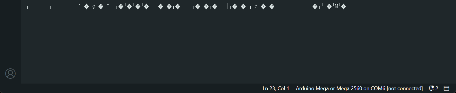
아스키 문자가 아닌 바이너리 데이터이기 때문에 Arduino IDE의 Serial Monitor를 통해 확인하면 알 수 없는 문자가 표시된다.


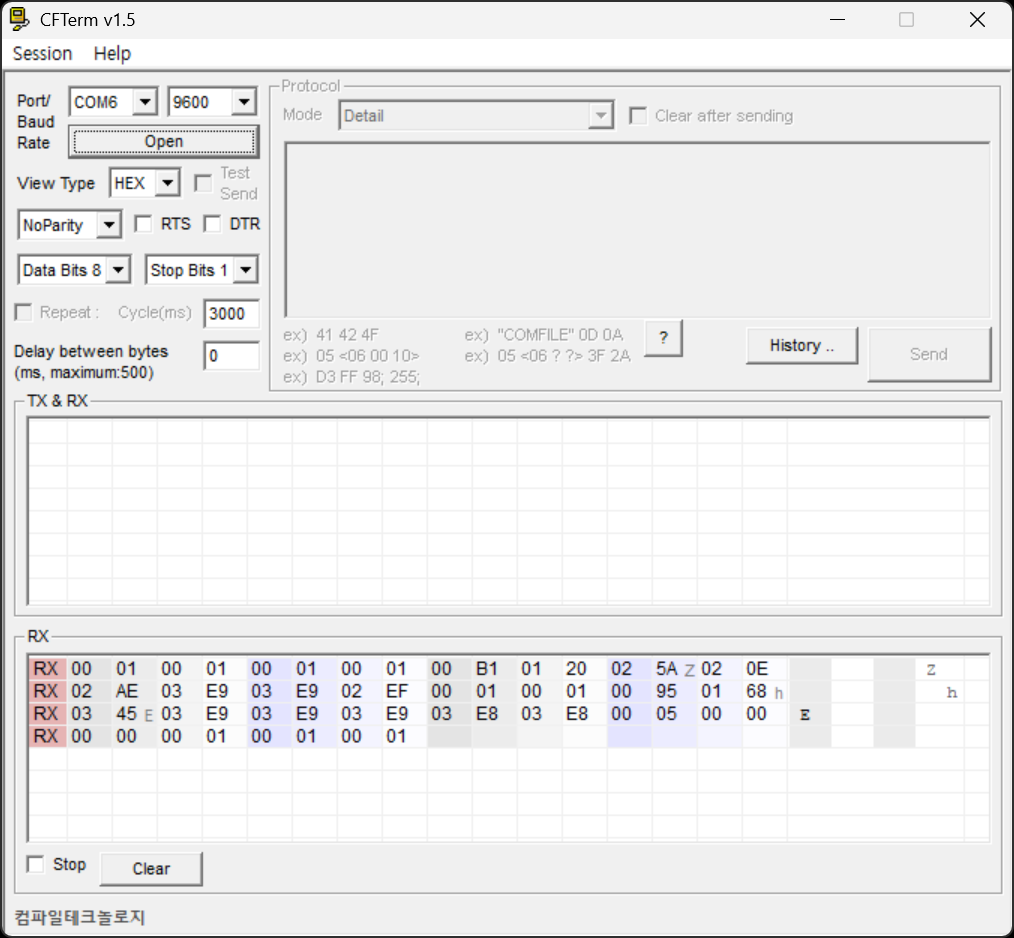
시리얼 통신용 프로그램을 사용하면 바이너리 데이터를 직접 확인할 수 있다.

1초당 2바이트씩 데이터를 읽는다. 처음 4초간은 압력이 없기 때문에 00 01이 4번 입력되고 5초에 177 Pa의 압력이 가해져 00 B1이 입력되었다.


센서가 출력하는 전류값이나 CFMEGA2가 읽는 전류값은 높은 정밀도를 가질 수 없을 것이다.

압력이 없을 때 센서를 통해 CFMEGA2에 들어온 ADC값이 처음엔 195였는데 몇 번 테스트하는 과정에서 196으로 바뀌었고 변환 과정을 거쳐 압력은 1로 표시되었다.  최대 압력일 때 ADC값도 최초 985에서 986으로 바뀌었다. 986은 변환식을 통해 1001이 된다.


예) (h): HEX, (d): DEC

■ 00 01(h): 1(d)

■ 00 B1(h): 177(d)

■ 01 20(h): 288(d)

...

■ 03 E9(h): 1001(d)


반응형
Posted by J-sean
: