반응형

콘솔에서 간단한 메세지를 주고 받는 서버, 클라이언트를 만들어 보자.


1
2
3
4
5
6
7
8
9
10
11
12
13
14
15
16
17
18
19
20
21
22
23
24
25
26
27
28
29
30
31
32
33
34
35
36
37
38
39
40
41
42
43
44
45
46
47
48
49
50
51
52
53
54
55
56
57
58
59
using System;
using System.Collections.Generic;
using System.Linq;
using System.Text;
using System.Threading.Tasks;
 
using System.Net;
using System.Net.Sockets;
 
namespace Server
{
    class Program
    {
        static void Main(string[] args)
        {
            IPEndPoint serverEndPoint = new IPEndPoint(IPAddress.Parse("192.168.0.100"), 7777);
            Socket server = new Socket(AddressFamily.InterNetwork, SocketType.Stream, ProtocolType.Tcp);
 
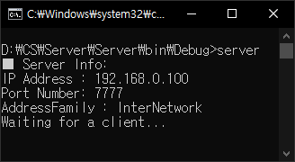
            Console.WriteLine("■ Server Info:");
            Console.WriteLine("IP Address : {0}", serverEndPoint.Address);
            Console.WriteLine("Port Number: {0}", serverEndPoint.Port);
            Console.WriteLine("AddressFamily : {0}", serverEndPoint.AddressFamily);
 
            // Associates a Socket with a local endpoint.
            server.Bind(serverEndPoint);
 
            // Places a Socket in a listening state.
            // Parameter: The maximum length of the pending connections queue.
            server.Listen(5);
 
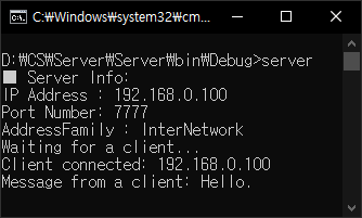
            Console.WriteLine("Waiting for a client...");
 
            // Creates a new Socket for a newly created connection.
            Socket client = server.Accept();
 
            IPEndPoint clientEndPoint = (IPEndPoint)client.RemoteEndPoint;
            Console.WriteLine("Client connected: {0}", clientEndPoint.Address);
 
            byte[] sendBuff = Encoding.UTF8.GetBytes("Connected to the server.");
            // Sends the specified number of bytes of data to a connected Socket, using the specified SocketFlags.
            client.Send(sendBuff, sendBuff.Length, SocketFlags.None);
 
            byte[] recvBuff = new byte[256];
            // Receives data from a bound Socket into a receive buffer.
            // Return: The number of bytes received.
            if (client.Receive(recvBuff) != 0)
            {
                Console.WriteLine("Message from a client: " + Encoding.UTF8.GetString(recvBuff));
            } else
            {
                Console.WriteLine("No message.");
            }
 
            // Closes the Socket connection and releases all associated resources.
            client.Close();
            server.Close();
        }
    }
}


서버 소스


1
2
3
4
5
6
7
8
9
10
11
12
13
14
15
16
17
18
19
20
21
22
23
24
25
26
27
28
29
30
31
32
using System;
using System.Collections.Generic;
using System.Linq;
using System.Text;
using System.Threading.Tasks;
 
using System.Net;
using System.Net.Sockets;
 
namespace Client
{
    class Program
    {
        static void Main(string[] args)
        {
            IPEndPoint serverEndPoint = new IPEndPoint(IPAddress.Parse("192.168.0.100"), 7777);
            Socket client = new Socket(AddressFamily.InterNetwork, SocketType.Stream, ProtocolType.Tcp);
 
            // Establishes a connection to a remote host.
            client.Connect(serverEndPoint);
            Console.WriteLine("Connecting to the server...");
 
            byte[] recvBuff = new byte[256];
            client.Receive(recvBuff);
            Console.WriteLine("Message from the server: " + Encoding.UTF8.GetString(recvBuff));
 
            client.Send(Encoding.UTF8.GetBytes("Hello."));
 
            client.Close();
        }
    }
}


클라이언트 소스


서버를 실행 시키면 클라이언트를 기다린다.


클라이언트를 실행 시키면 대기중인 서버와 연결되고 메세지를 주고 받는다.


서버에도 클라이언트로부터 받은 메세지가 표시된다.


반응형
Posted by J-sean
:
반응형

아두이노로 간단히 RF433MHz 통신이 가능하다.


왼쪽이 리시버, 오른쪽이 트랜스미터다.


송신기와 수신기를 아두이노에 연결해 준다. RadioHead Packet Radio library를 다운받고 아래와 같이 아두이노 라이브러리에 복사한다.


특별한 설치 과정은 없다. 그냥 복사한다.


1
2
3
4
5
6
7
8
9
10
11
12
13
14
15
16
17
18
19
20
21
22
23
24
25
26
27
28
29
30
31
32
33
34
35
36
37
38
39
40
41
42
43
44
// ask_transmitter.pde
// -*- mode: C++ -*-
// Simple example of how to use RadioHead to transmit messages
// with a simple ASK transmitter in a very simple way.
// Implements a simplex (one-way) transmitter with an TX-C1 module
// Tested on Arduino Mega, Duemilanova, Uno, Due, Teensy, ESP-12
 
#include <RH_ASK.h>
#ifdef RH_HAVE_HARDWARE_SPI
#include <SPI.h> // Not actually used but needed to compile
#endif
 
RH_ASK driver;
// RH_ASK driver(2000, 4, 5, 0); // ESP8266 or ESP32: do not use pin 11 or 2
// RH_ASK driver(2000, 3, 4, 0); // ATTiny, RX on D3 (pin 2 on attiny85) TX on D4 (pin 3 on attiny85), 
// RH_ASK driver(2000, PD14, PD13, 0); STM32F4 Discovery: see tx and rx on Orange and Red LEDS
 
void setup()
{
  #ifdef RH_HAVE_SERIAL
    Serial.begin(9600);    // Debugging only
  #endif
    if (!driver.init())
  #ifdef RH_HAVE_SERIAL
      Serial.println("init failed");
  #else
      ;
  #endif
    else
      Serial.println("init succeeded");
}
 
void loop()
{
  const char *msg = "Hello Wireless World!";
 
  driver.send((uint8_t *)msg, strlen(msg));
  driver.waitPacketSent();
  #ifdef RH_HAVE_SERIAL
      Serial.println("Message sent.");
  #endif
  
  delay(200);
}


Transmitter 소스를 컴파일하고 아두이노에 업로드한다.


1
2
3
4
5
6
7
8
9
10
11
12
13
14
15
16
17
18
19
20
21
22
23
24
25
26
27
28
29
30
31
32
33
34
35
36
37
38
39
40
41
42
43
44
45
46
47
48
49
50
51
52
// ask_receiver.pde
// -*- mode: C++ -*-
// Simple example of how to use RadioHead to receive messages
// with a simple ASK transmitter in a very simple way.
// Implements a simplex (one-way) receiver with an Rx-B1 module
// Tested on Arduino Mega, Duemilanova, Uno, Due, Teensy, ESP-12
 
#include <RH_ASK.h>
#ifdef RH_HAVE_HARDWARE_SPI
#include <SPI.h> // Not actually used but needed to compile
#endif
 
RH_ASK driver;
// RH_ASK driver(2000, 4, 5, 0); // ESP8266 or ESP32: do not use pin 11 or 2
// RH_ASK driver(2000, 3, 4, 0); // ATTiny, RX on D3 (pin 2 on attiny85) TX on D4 (pin 3 on attiny85), 
// RH_ASK driver(2000, PD14, PD13, 0); STM32F4 Discovery: see tx and rx on Orange and Red LEDS
 
void setup()
{
  #ifdef RH_HAVE_SERIAL
    Serial.begin(9600);    // Debugging only
  #endif
    if (!driver.init())
      
  #ifdef RH_HAVE_SERIAL
      Serial.println("init failed");
  #else
      ;
  #endif
    else
      Serial.println("init succeeded");
}
 
void loop()
{
  uint8_t buf[RH_ASK_MAX_MESSAGE_LEN];
  memset(buf, 0, RH_ASK_MAX_MESSAGE_LEN);
  uint8_t buflen = sizeof(buf);
 
  if (driver.recv(buf, &buflen)) // Non-blocking
  {
    // Message with a good checksum received, dump it.
    driver.printBuffer("Got:", buf, buflen);
    #ifdef RH_HAVE_SERIAL
      String message = (char*)buf;
      Serial.print("Message: ");
      Serial.println(message);
    #endif
  }
 
  delay(200);
}


Receiver 소스를 컴파일하고 아두이노에 업로드한다.


송신기에서는 계속 메세지를 보낸다.


송신기에서 보낸 메세지를 수신기에서 받는다. printBuffer()로 출력한 메세지는 각 문자의 아스키 코드값이다.


void RHGenericDriver::printBuffer(const char* prompt, const uint8_t* buf, uint8_t len)

Parameters

[in] prompt string to preface the print

[in] buf Location of the buffer to print

[in] len Length of the buffer in octets.


Prints a data buffer in HEX. For diagnostic use


※ 참고: RH_ASK Class Reference


반응형
Posted by J-sean
:
반응형

Windows API(CreateFile)을 이용해 간단히 아두이노와 시리얼 통신을 할 수 있다.


1
2
3
4
5
6
7
8
9
10
11
12
13
14
15
16
17
18
19
20
21
22
23
24
25
26
27
28
29
30
31
32
char state;
 
void setup() {
  // put your setup code here, to run once:
  pinMode(LED_BUILTIN, OUTPUT);
  Serial.begin(9600);
  Serial.println("Arduino ready.");
}
 
void loop() {
  // put your main code here, to run repeatedly:
  if (Serial.available())
  {
    state = Serial.read();
    while (Serial.available())
    {
      Serial.read();  // 첫 번째 문자만 입력받고 나머지는 버린다.
    }
    
    if (state == '0')
    {
      digitalWrite(LED_BUILTIN, LOW);
      Serial.println("LED OFF");
    } else
    {
      digitalWrite(LED_BUILTIN, HIGH);
      Serial.println("LED ON");
    }
  }
 
  delay(100);
}


위 소스를 컴파일 하고 아두이노에 업로드 한다. 시리얼 모니터를 통해서도 Builtin LED를 제어할 수 있다.


1
2
3
4
5
6
7
8
9
10
11
12
13
14
15
16
17
18
19
20
21
22
23
24
25
26
27
28
29
30
31
32
33
34
35
36
37
38
39
40
41
#ifndef SERIALCLASS_H_INCLUDED
#define SERIALCLASS_H_INCLUDED
 
#define ARDUINO_WAIT_TIME 2000
 
#include <windows.h>
#include <stdio.h>
#include <stdlib.h>
 
class Serial
{
private:
    //Serial comm handler
    HANDLE hSerial;
    //Connection status
    bool connected;
    //Get various information about the connection
    COMSTAT status;
    //Keep track of last error
    DWORD errors;
 
public:
    //Initialize Serial communication with the given COM port
    Serial(const char* portName);
    //Close the connection
    ~Serial();
    //Read data in a buffer, if nbChar is greater than the
    //maximum number of bytes available, it will return only the
    //bytes available. The function return -1 when nothing could
    //be read, the number of bytes actually read.
    int ReadData(char* buffer, unsigned int nbChar);
    //Writes data from a buffer through the Serial connection
    //return true on success.
    bool WriteData(const char* buffer, unsigned int nbChar);
    //Check if we are actually connected
    bool IsConnected();
 
 
};
 
#endif // SERIALCLASS_H_INCLUDED


Serial class header.


1
2
3
4
5
6
7
8
9
10
11
12
13
14
15
16
17
18
19
20
21
22
23
24
25
26
27
28
29
30
31
32
33
34
35
36
37
38
39
40
41
42
43
44
45
46
47
48
49
50
51
52
53
54
55
56
57
58
59
60
61
62
63
64
65
66
67
68
69
70
71
72
73
74
75
76
77
78
79
80
81
82
83
84
85
86
87
88
89
90
91
92
93
94
95
96
97
98
99
100
101
102
103
104
105
106
107
108
109
110
111
112
113
114
115
116
117
118
119
120
121
122
123
124
125
126
127
128
129
130
131
132
133
134
135
136
137
138
139
140
141
142
143
144
145
146
147
#include "SerialHeader.h"
 
Serial::Serial(const char* portName)
{
    //We're not yet connected
    this->connected = false;
 
    //Try to connect to the given port throuh CreateFile
    //CreateFile may need to be replaced with CreateFileA or...
    //Project - XXX Properties - Configuration Properties - Advanced - Character Set - Use Multi-Byte Character Set
    this->hSerial = CreateFileA(portName,
        GENERIC_READ | GENERIC_WRITE,
        0,
        NULL,
        OPEN_EXISTING,
        FILE_ATTRIBUTE_NORMAL,
        NULL);
 
    //Check if the connection was successfull
    if (this->hSerial == INVALID_HANDLE_VALUE)
    {
        //If not success full display an Error
        if (GetLastError() == ERROR_FILE_NOT_FOUND) {
 
            //Print Error if neccessary
            printf("ERROR: Handle was not attached. Reason: %s not available.\n", portName);
 
        }
        else
        {
            printf("ERROR!!!");
        }
    }
    else
    {
        //If connected we try to set the comm parameters
        DCB dcbSerialParams = { 0 };
 
        //Try to get the current
        if (!GetCommState(this->hSerial, &dcbSerialParams))
        {
            //If impossible, show an error
            printf("failed to get current serial parameters!");
        }
        else
        {
            //Define serial connection parameters for the arduino board
            dcbSerialParams.BaudRate = CBR_9600;
            dcbSerialParams.ByteSize = 8;
            dcbSerialParams.StopBits = ONESTOPBIT;
            dcbSerialParams.Parity = NOPARITY;
            //Setting the DTR to Control_Enable ensures that the Arduino is properly
            //reset upon establishing a connection
            dcbSerialParams.fDtrControl = DTR_CONTROL_ENABLE;
 
            //Set the parameters and check for their proper application
            if (!SetCommState(hSerial, &dcbSerialParams))
            {
                printf("ALERT: Could not set Serial Port parameters");
            }
            else
            {
                //If everything went fine we're connected
                this->connected = true;
                //Flush any remaining characters in the buffers 
                PurgeComm(this->hSerial, PURGE_RXCLEAR | PURGE_TXCLEAR);
                //We wait 2s as the arduino board will be reseting
                Sleep(ARDUINO_WAIT_TIME);
            }
        }
    }
 
}
 
Serial::~Serial()
{
    //Check if we are connected before trying to disconnect
    if (this->connected)
    {
        //We're no longer connected
        this->connected = false;
        //Close the serial handler
        CloseHandle(this->hSerial);
    }
}
 
int Serial::ReadData(char* buffer, unsigned int nbChar)
{
    //Number of bytes we'll have read
    DWORD bytesRead;
    //Number of bytes we'll really ask to read
    unsigned int toRead;
 
    //Use the ClearCommError function to get status info on the Serial port
    ClearCommError(this->hSerial, &this->errors, &this->status);
 
    //Check if there is something to read
    if (this->status.cbInQue > 0)
    {
        //If there is we check if there is enough data to read the required number
        //of characters, if not we'll read only the available characters to prevent
        //locking of the application.
        if (this->status.cbInQue > nbChar)
        {
            toRead = nbChar;
        }
        else
        {
            toRead = this->status.cbInQue;
        }
 
        //Try to read the require number of chars, and return the number of read bytes on success
        memset(buffer, 0, nbChar);
        if (ReadFile(this->hSerial, buffer, toRead, &bytesRead, NULL))
        {
            return bytesRead;
        }
 
    }
 
    //If nothing has been read, or that an error was detected return 0
    return 0;
 
}
 
 
bool Serial::WriteData(const char* buffer, unsigned int nbChar)
{
    DWORD bytesSend;
 
    //Try to write the buffer on the Serial port
    if (!WriteFile(this->hSerial, (void*)buffer, nbChar, &bytesSend, 0))
    {
        //In case it don't work get comm error and return false
        ClearCommError(this->hSerial, &this->errors, &this->status);
 
        return false;
    }
    else
        return true;
}
 
bool Serial::IsConnected()
{
    //Simply return the connection status
    return this->connected;
}


Serial class source.


1
2
3
4
5
6
7
8
9
10
11
12
13
14
15
16
17
18
19
20
21
22
23
24
25
26
27
28
29
30
31
32
33
34
35
36
37
38
39
40
41
42
43
#include <iostream>
#include "SerialHeader.h"
 
using namespace std;
 
int main()
{
    Serial* ser = new Serial("\\\\.\\COM3");
    char message[255];    
 
    if (ser->IsConnected()) {
        cout << "Serial Communication Connected." << endl;
        // memset(message, 0, sizeof(message));
        // Serial::ReadData() 내부에서 memset이 실행된다.
        ser->ReadData(message, sizeof(message));
        cout << "Message from Arduino: " << message << endl;
    } else {
        cout << "Device can not be found or can not be configured." << endl;
 
        return 0;
    }
    
    while (true) {
        cout << "0: Off, 1 : On, q(Q) : Quit" << endl << "Choose : ";        
        cin >> message;
 
        if (!strcmp(message, "q"|| !strcmp(message, "Q")) {
            break;
        } else if (!strcmp(message, "0")) {            
            ser->WriteData("0"1);
            Sleep(200); // 아두이노와의 시리얼 통신을 위한 대기 시간.            
            ser->ReadData(message, sizeof(message));
            cout << "Message from Arduino: " << message << endl;
        } else {
            ser->WriteData("1"1);
            Sleep(200); // 아두이노와의 시리얼 통신을 위한 대기 시간.            
            ser->ReadData(message, sizeof(message));
            cout << "Message from Arduino: " << message << endl;
        }
    }
 
    return 0;
}


Windows에서 위 소스를 실행하면 연결된 아두이노의 Builtin LED를 제어할 수 있다.


※ 참고: Arduino and C++ (for Windows)


반응형
Posted by J-sean
:
반응형

nRF24L01 모듈은 Serial Peripheral Interface(SPI) 프로토콜을 사용하여 2.4GHz 무선 통신이 가능하다.


중국에서 구매한 nRF24L01 모듈 2개.


8개의 핀이 있다.


nRF24L01의 핀맵.


아두이노의 핀맵. nRF24L01과 연결할 핀을 확인 한다.


이렇게 연결 한다.


[nRF24L01 - Arduino]

VCC - 3.3V

GND - GND

CSN - 8

CE - 7

MOSI - 11

SCK - 13

IRQ - N/A

MISO - 12


통신을 해야 하므로 2개 모두 연결해 준다.


수신 프로그램을 컴파일 하고 아두이노에 업로드 한다.


송신 프로그램을 컴파일 하고 다른 아두이노에 업로드 한다.


수신 프로그램이 업로드된 아두이노의 시리얼 모니터를 확인해 보자.

통신이 잘 안된다면 10μF 커패시터를 연결 하고 3.3V 외부 전원을 사용 하자.


GND is the Ground Pin. It is usually marked by encasing the pin in a square so it can be used as a reference for identifying the other pins.


VCC supplies power for the module. This can be anywhere from 1.9 to 3.9 volts. You can connect it to 3.3V output from your Arduino. Remember connecting it to 5V pin will likely destroy your nRF24L01+ module!


CE (Chip Enable) is an active-HIGH pin. When selected the nRF24L01 will either transmit or receive, depending upon which mode it is currently in.


CSN (Chip Select Not) is an active-LOW pin and is normally kept HIGH. When this pin goes low, the nRF24L01 begins listening on its SPI port for data and processes it accordingly.


SCK (Serial Clock) accepts clock pulses provided by the SPI bus Master.


MOSI (Master Out Slave In) is SPI input to the nRF24L01.


MISO (Master In Slave Out) is SPI output from the nRF24L01.


IRQ is an interrupt pin that can alert the master when new data is available to process.


반응형
Posted by J-sean
: