MASM 6.11

Assembly 2022. 12. 16. 15:31 |
반응형

DOS에서 실행 가능한 마지막 MASM 버전 6.11


masm611.zip
11.29MB

문서 포함


Microsoft Macro Assembler 6.11.zip
7.03MB

3.5인치 플로피 디스크 IMG 파일


반응형
Posted by J-sean
:
반응형

콘솔에서 간단한 메세지를 주고 받는 서버, 클라이언트를 만들어 보자.


1
2
3
4
5
6
7
8
9
10
11
12
13
14
15
16
17
18
19
20
21
22
23
24
25
26
27
28
29
30
31
32
33
34
35
36
37
38
39
40
41
42
43
44
45
46
47
48
49
50
51
52
53
54
55
56
57
58
59
using System;
using System.Collections.Generic;
using System.Linq;
using System.Text;
using System.Threading.Tasks;
 
using System.Net;
using System.Net.Sockets;
 
namespace Server
{
    class Program
    {
        static void Main(string[] args)
        {
            IPEndPoint serverEndPoint = new IPEndPoint(IPAddress.Parse("192.168.0.100"), 7777);
            Socket server = new Socket(AddressFamily.InterNetwork, SocketType.Stream, ProtocolType.Tcp);
 
            Console.WriteLine("■ Server Info:");
            Console.WriteLine("IP Address : {0}", serverEndPoint.Address);
            Console.WriteLine("Port Number: {0}", serverEndPoint.Port);
            Console.WriteLine("AddressFamily : {0}", serverEndPoint.AddressFamily);
 
            // Associates a Socket with a local endpoint.
            server.Bind(serverEndPoint);
 
            // Places a Socket in a listening state.
            // Parameter: The maximum length of the pending connections queue.
            server.Listen(5);
 
            Console.WriteLine("Waiting for a client...");
 
            // Creates a new Socket for a newly created connection.
            Socket client = server.Accept();
 
            IPEndPoint clientEndPoint = (IPEndPoint)client.RemoteEndPoint;
            Console.WriteLine("Client connected: {0}", clientEndPoint.Address);
 
            byte[] sendBuff = Encoding.UTF8.GetBytes("Connected to the server.");
            // Sends the specified number of bytes of data to a connected Socket, using the specified SocketFlags.
            client.Send(sendBuff, sendBuff.Length, SocketFlags.None);
 
            byte[] recvBuff = new byte[256];
            // Receives data from a bound Socket into a receive buffer.
            // Return: The number of bytes received.
            if (client.Receive(recvBuff) != 0)
            {
                Console.WriteLine("Message from a client: " + Encoding.UTF8.GetString(recvBuff));
            } else
            {
                Console.WriteLine("No message.");
            }
 
            // Closes the Socket connection and releases all associated resources.
            client.Close();
            server.Close();
        }
    }
}


서버 소스


1
2
3
4
5
6
7
8
9
10
11
12
13
14
15
16
17
18
19
20
21
22
23
24
25
26
27
28
29
30
31
32
using System;
using System.Collections.Generic;
using System.Linq;
using System.Text;
using System.Threading.Tasks;
 
using System.Net;
using System.Net.Sockets;
 
namespace Client
{
    class Program
    {
        static void Main(string[] args)
        {
            IPEndPoint serverEndPoint = new IPEndPoint(IPAddress.Parse("192.168.0.100"), 7777);
            Socket client = new Socket(AddressFamily.InterNetwork, SocketType.Stream, ProtocolType.Tcp);
 
            // Establishes a connection to a remote host.
            client.Connect(serverEndPoint);
            Console.WriteLine("Connecting to the server...");
 
            byte[] recvBuff = new byte[256];
            client.Receive(recvBuff);
            Console.WriteLine("Message from the server: " + Encoding.UTF8.GetString(recvBuff));
 
            client.Send(Encoding.UTF8.GetBytes("Hello."));
 
            client.Close();
        }
    }
}


클라이언트 소스


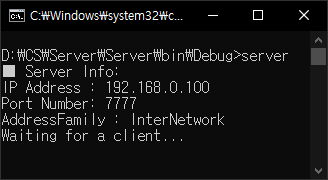
서버를 실행 시키면 클라이언트를 기다린다.


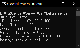
클라이언트를 실행 시키면 대기중인 서버와 연결되고 메세지를 주고 받는다.


서버에도 클라이언트로부터 받은 메세지가 표시된다.


반응형
Posted by J-sean
:
반응형

Qt6는 더 이상 오프라인 인스톨러를 제공하지 않는다. 오픈소스 온라인 인스톨러를 다운 받고 설치하자.

예전에는 Qt에 가입할 필요는 없었지만 지금은 아이디가 필요하다. 설치 전 미리 가입하자.


Latest releases - Qt - Qt 6.X.X - MSVC 2019 64-bit 만 선택하고 Developer and Designer Tools는 기본 상태 그대로 설치한다.


Qt 설치가 완료되면 Visual Studio - Extensions - Manage Extensions를 클릭한다.


Online - Visual Studio Marketplace에서 qt를 검색하고 Qt Visual Studio Tools를 설치한다. (Visual Studio 재시작이 필요하다)


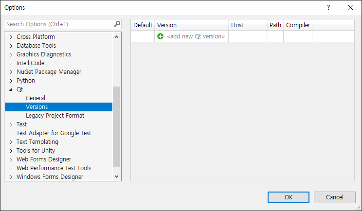
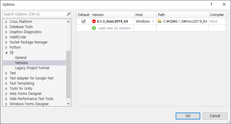
Extensions - Qt VS Tools - Options를 클릭한다.


사용할 Qt를 추가해 주어야 한다. +아이콘을 클릭하고 Path를 클릭한다.


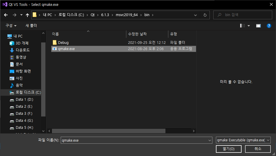
Qt가 설치된 디렉토리에서 qmake.exe 파일을 선택한다.


위 그림과 같이 설정 되었다면 OK를 클릭한다.


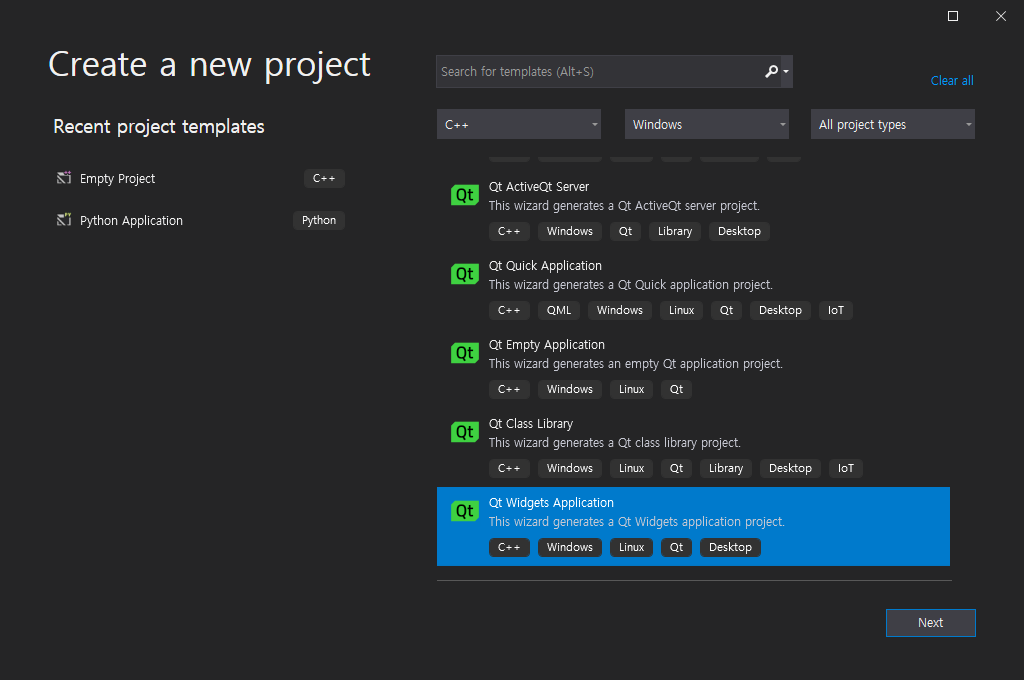
Qt Widgets Application 프로젝트를 만들자.


프로젝트 이름, 위치등을 지정하고 Create 버튼을 클릭한다.


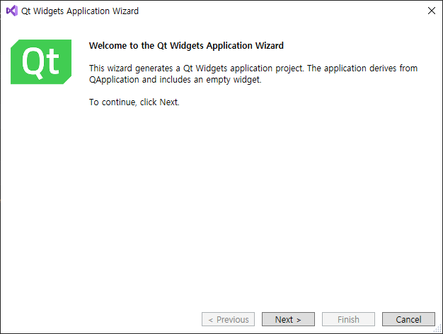
Qt Widgets Application Wizard가 실행된다.


적당한 옵션을 선택한다.


적당한 옵션을 지정하고 Finish 버튼을 클릭한다.


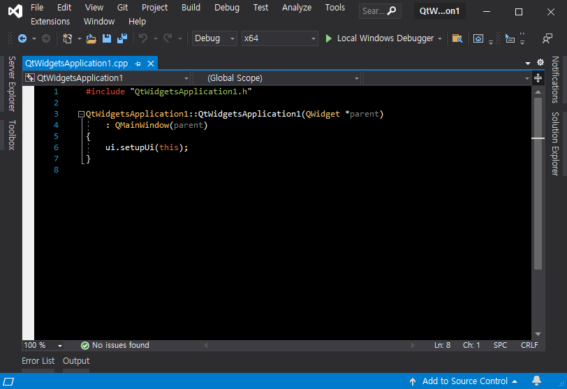
소스파일이 표시된다.


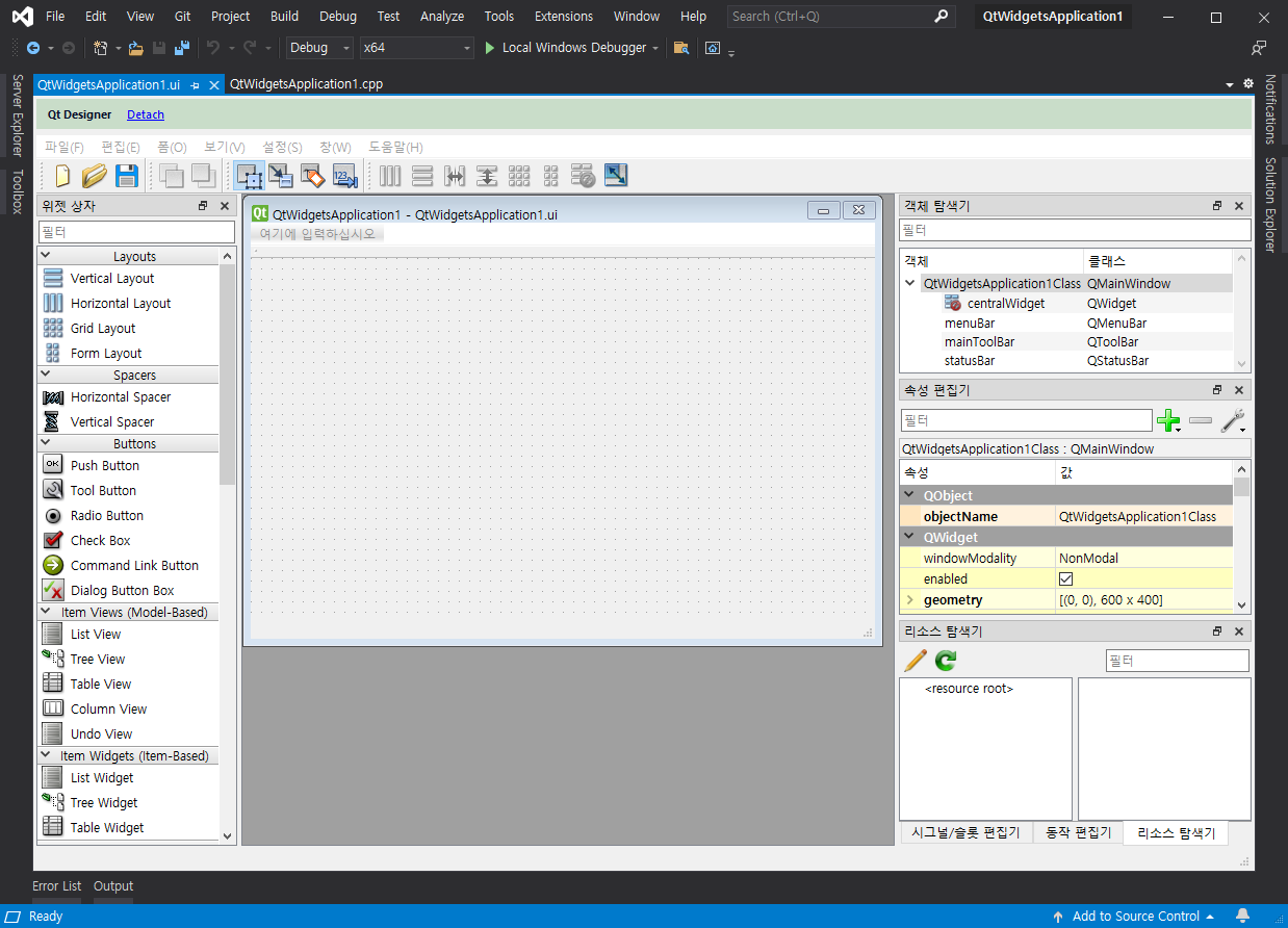
Solution Explorer에서 UI 디자인 파일을 더블 클릭한다.


UI 디자인 화면이 표시된다.


Project Property Pages - Configuration Properties - C/C++ - Language를 클릭한다


Qt6는 C++ 17을 사용한다.


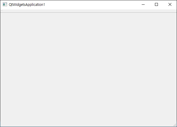
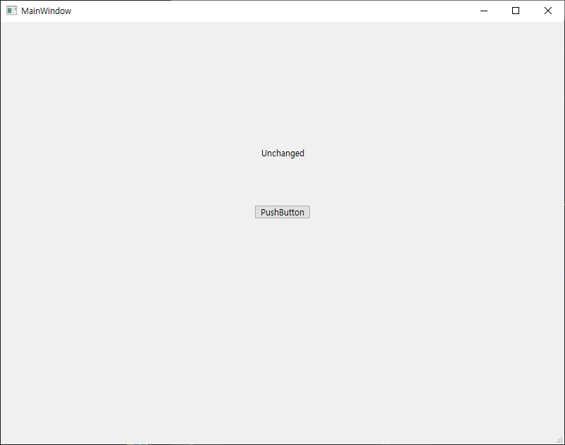
소스나 UI 수정없이 빌드하고 실행했을 때 위와 같은 위도우가 뜨면 성공이다. 


그런데 UI 디자인툴에서 PushButton - 우클릭을 해도 'Go to slot...'에 해당하는 명령어가 나오지 않는다.

그 뿐만 아니라 프로젝트 생성시 Qt Creator와 생성되는 파일도 다르고 코드를 작성해도 이해할 수 없는 방식으로 작동한다.


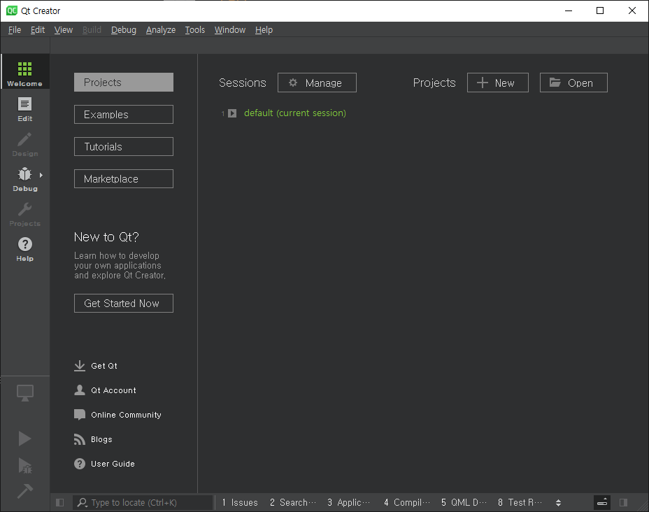
Qt Creator를 실행하고 Projects - New를 클릭한다.


Application (Qt) - Qt Widgets Application을 선택한다. 나머지 옵션은 적당히 선택한다.


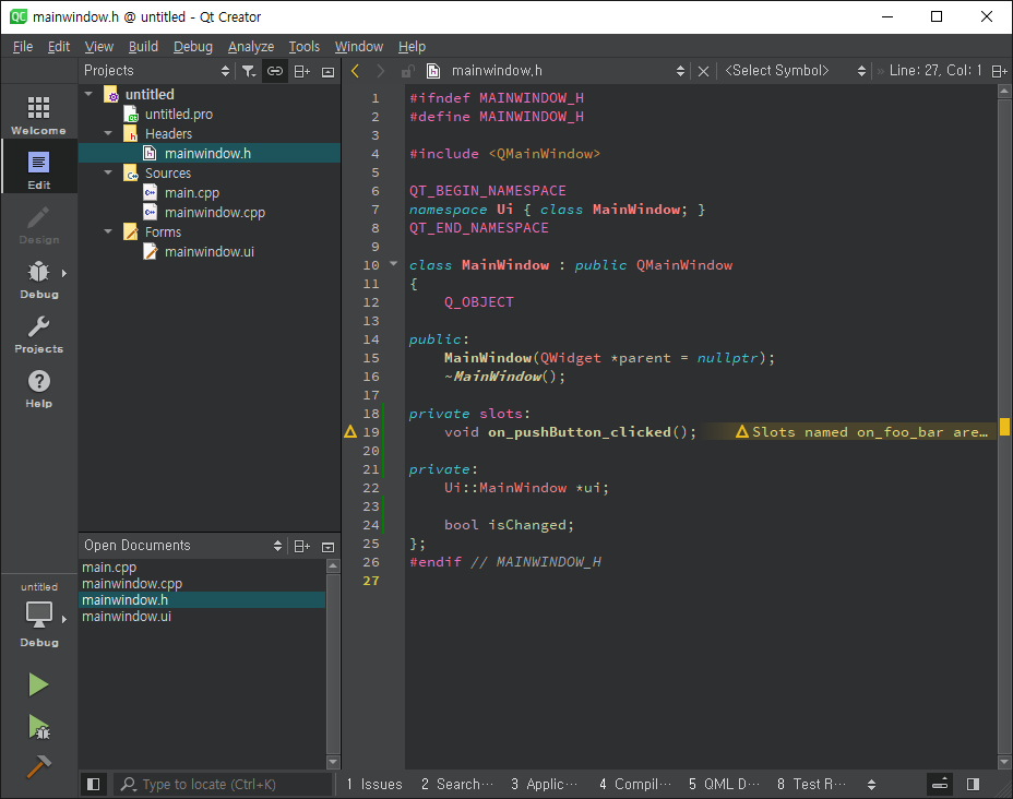
Visual Studio와는 약간 다른 파일들이 생성되었다.


Forms - mainwindow.ui를 더블 클릭한다.


Label과 Pushbutton을 적당히 배치하고 Pushbutton에서 우클릭 - Go to slot...을 클릭한다.


clicked()를 선택하고 OK 버튼을 클릭한다.


mainwindow.cpp에 on_pushButton_clicked()가 생성되었다. (mainwindow.h 파일도 변경된다)


mainwindow.h 파일을 위와 같이 수정한다.


mainwindow.cpp 파일을 위와 같이 수정하고 빌드한다.


프로젝트를 실행하면 위와 같은 윈도우가 나타난다.


Pushbutton을 클릭하면 Label이 변경된다.


Pushbutton을 클릭할때마다 Label은 계속 변경된다.

다른 간단한 예제는 아래 링크를 참고한다.

2019.01.16 - [C, C++] - Qt 설치 및 간단한 사용 예

2019.02.21 - [C, C++] - Qt 스프라이트 애니매이션


반응형
Posted by J-sean
:
반응형

USBASP로 ATtiny13을 프로그래밍 할 수 있다. Arduino를 이용한 프로그래밍과 기본적인 설정 방법은 아래 링크를 참고 한다.


2020/04/02 - [Raspberry Pi & Arduino] - Programming ATtiny13 with Arduino Uno - 아두이노로 ATtiny13 프로그래밍 하기


AliExpress에서 구매한 USBASP.


Adaptor와 함께 구매 했다.


컴퓨터에 연결 한다.


드라이버가 설치되지 않았다면 제대로 인식하지 못한다.


https://zadig.akeo.ie/

위 링크에서 Zadig를 다운 받는다.

zadig-2.5.exe
4.92MB


드라이버를 설치 한다.


장치가 제대로 인식 된다.


ATtiny13에 기본적인 Blink 예제를 프로그래밍 할 수 있도록 케이블을 연결 한다.

USBASP RESET - ATtiny pin 1

USBASP MOSI - ATtiny pin 5

USBASP MISO - ATtiny pin 6

USBASP SCK - ATtiny pin 7

USBASP 5V - ATtiny pin 8

USBASP GND - ATtiny pin 4


Optional:

ATtiny pin4(GND) - Negative side of the LED

ATTiny pin 3 - Resistor (330 Ohm) - Positive side of the LED


프로그램을 컴파일 하고 업로드 해도 warning이 발생하고 제대로 작동 하지 않는다. USBASP의 Firmware를 업데이트 해야 한다.


https://sourceforge.net/projects/ardude/

위 링크에서 Arduino AVR Dude Programmer를 다운 받고 설치한다. (설치하지 않고 cab 파일의 압축만 풀어도 상관 없다)

Arduino AVR Dude Programmer.zip
1.99MB


https://www.fischl.de/usbasp/

위 링크에서 usbasp.2011-05-28.tar.gz를 다운 받고 압축을 풀어서 usbasp.atmega8.2011-05-28.hex파일을 Arduino AVR Dude Programmer가 있는 폴더에 복사 한다. (USBASP의 칩셋이 ATMEGA8인지 확인 한다)

usbasp.2011-05-28.tar.gz
0.51MB


컴퓨터에 Arduino만 연결한 상태에서 File - Examples - 11. ArduinoISP - ArduinoISP를 컴파일 하고 업로드 한다.


USBASP의 Firmware를 업데이트 할 수 있도록 케이블을 연결 한다.

USBASP RESET - Arduino pin 10

USBASP MOSI - Arduino pin 11

USBASP MISO - Arduino pin 12

USBASP SCK - Arduino pin 13

USBASP 5V - Arduino 5V

USBASP GND - Arduino GND


Arduino RESET - (+) 10㎌ Capacitor (-) - Arduino GND (Capacitor를 연결하지 않으면 Firmware 업데이트가 제대로 되지 않는다)

USBASP JP1(JP2로 표시된 제품도 있다) 연결


avrdude가 있는 폴더(Arduino AVR Dude Programmer를 설치한 폴더)로 이동 해서 아래 명령어를 실행 한다.

avrdude -C avrdude.conf -c avrisp -P COM3 -b 19200 -p m8 -v

(COM 포트는 실제 포트를 적어준다.)


이상이 없다면 AVR device initialized and ready to accept instructions라는 메세지가 나온다.


아래 명령어를 실행 한다.

avrdude -C avrdude.conf -c avrisp -P COM3 -b 19200 -p m8 -U flash:w:usbasp.atmega8.2011-05-28.hex

Verify까지 완료되면 USBASP의 Firmware 업데이트가 끝난다.


USBASP로 Blink 예제를 프로그래밍 할 수 있도록 케이블을 다시 연결 한다.

USBASP RESET - ATtiny pin 1

USBASP MOSI - ATtiny pin 5

USBASP MISO - ATtiny pin 6

USBASP SCK - ATtiny pin 7

USBASP 5V - ATtiny pin 8

USBASP GND - ATtiny pin 4


Optional:

ATtiny pin 4(GND) - Negative side of the LED

ATTiny pin 3 - Resistor (330 Ohm) - Positive side of the LED


Programmer: "USBasp (slow)"로 설정 한다. USBasp로 설정 하면 에러가 발생 한다.


컴파일 하고 업로드 한다.


ATtiny13에 프로그램이 업로드 되고 정상 작동 한다.


반응형
Posted by J-sean
:
반응형

ESP32-CAM에는 프로그래머 칩이 없기 때문에 보통 USB to UART Converter를 이용해 프로그래밍 한다. 하지만 아두이노 보드가 있다면 Converter 없이 ESP32-CAM에 프로그래밍 할 수 있다.


2020/11/15 - [Raspberry Pi & Arduino] - NodeMCU(ESP-12E/ESP8266) LED Control Server Programming


USB to UART Converter


eBay에 주문 후 약 한 달 반이 걸려 도착한 ESP32-CAM. 카메라와 함께 작은 정전기방지 비닐에 포장되어 도착했다.


ESP32-CAM 보드


뒷면


Flat Flexible Cable에 8225N V2.0 171026라고 적힌 카메라


뒷면


누군지 기억도 안나는 사람의 명함과 함께 크기 비교


카메라를 연결 하기 위해 저 검은 latch를 들어 올려 열어야 한다.


이렇게.


카메라 케이블을 삽입하고 닫아 준다.


아두이노와 ESP32-CAM을 케이블로 연결한다. 내 가짜 아두이노... ㅠㅠ


Arduino 5V to ESP32-CAM 5V

Arduino GND to ESP32-CAM GND

Arduino RX to ESP32-CAM U0R

Arduino TX to ESP32-CAM U0T

Arduino RESET to Arduino GND

ESP32-CAM IO0 to ESP32-CAM GND


Arduino를 실행하고 File - Preferences 클릭.


Additional Boards Manager URLs에 아래 주소를 입력하고 OK클릭

https://dl.espressif.com/dl/package_esp32_index.json


Tools - Board: "Arduino Uno" - Boards Manager... 클릭


'esp32'를 검색하고 Install 클릭


Board Manager에서 esp32 설치가 완료 되면 위와 같이 설정을 바꿔준다.


Board: ESP32 Wrover Module"

Upload Speed: "115200"

Flash Frequency: "40MHz"

Flash Mode: "QIO"

Partition Scheme: "Huge APP (3MB No OTA/1MB SPIFFS)"

Core Debug Level: "None"

Port: "COM4"(아두이노가 연결된 포트)

Programmer: "AVR ISP"


File - Examples - ESP32 - Camera - CameraWebServer를 클릭 하면 카메라 웹 서버 코드가 로드 된다.


1
2
3
4
5
6
7
8
9
10
11
// Select camera model
#define CAMERA_MODEL_WROVER_KIT
//#define CAMERA_MODEL_ESP_EYE
//#define CAMERA_MODEL_M5STACK_PSRAM
//#define CAMERA_MODEL_M5STACK_WIDE
//#define CAMERA_MODEL_AI_THINKER
 
#include "camera_pins.h"
 
const char* ssid = "*********";
const char* password = "*********";


카메라 웹 서버 코드의 일부


1
2
3
4
5
6
7
8
9
10
11
// Select camera model
//#define CAMERA_MODEL_WROVER_KIT
//#define CAMERA_MODEL_ESP_EYE
//#define CAMERA_MODEL_M5STACK_PSRAM
//#define CAMERA_MODEL_M5STACK_WIDE
#define CAMERA_MODEL_AI_THINKER
 
#include "camera_pins.h"
 
const char* ssid = "my_ssid";
const char* password = "my_password";


대부분 AI_THINKER 카메라를 사용 하므로 #define CAMERA_MODEL_WROVER_KIT은 주석 처리하고 #define CAMERA_MODEL_AI_THINKER을 주석 해제 한다. ssid와 password 부분은 자신의 인터넷 ssid와 password에 맞게 수정한다.


소스를 컴파일하고 ESP32-CAM에 업로드 한다.


업로드가 완료 되면 ESP32-CAM IO0 와 ESP32-CAM GND를 연결한 케이블을 제거 한다.


Tools - Serial Monitor 클릭


Baud Rate을 115200으로 맞춘다.


ESP32-CAM 뒷면의 RST 버튼을 눌러 준다.


RST 버튼을 누르면 잠시 후 Serial Monitor 마지막 줄에 카메라 웹 서버의 주소가 표시 된다.


인터넷 브라우저로 카메라 웹 서버에 접속하면 위와 같은 화면이 나온다. Start Stream 버튼을 클릭 한다.


카메라에 찍히는 영상이 바로 스트리밍 된다. Resolution, Quality, Brightness, Contrast, H-Mirror, V-Flip, Face Detection등의 설정을 변경 할 수 있다.


Serial Monitor에는 스트리밍 상황이 표시 된다.


영상 스트리밍만 확인 하고 싶다면 아래와 같은 형식으로 접속 한다.

http://웹서버주소:81/stream

http://192.168.0.42:81/stream


ESP32-CAM에 프로그램 업로드가 완료되면 5V 전원만 있어도 동작한다. 5V 배터리나 건전지를 사용해도 되고 USB 케이블에서 5V를 받아와도 된다. 컴퓨터 USB 케이블은 5V를 사용한다.


빨간색: 5V

검정색: GND


빨간색 선은 5V에 연결하고 검정색 선은 GND에 연결한다.


ESP32-CAM이 연결된 USB 케이블을 컴퓨터에 연결하면 잘 작동 한다.


반응형
Posted by J-sean
: